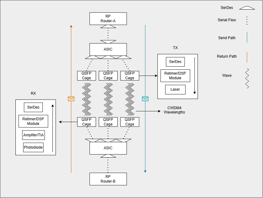
Full Packet Walkthrough
A ping between directly connected Router A and Router B, over a 100G CWDM4 optical link — showing how everything comes together.
Scenario
Router A pings Router B. The two routers are directly connected via a QSFP28 100G CWDM4 optical link.
(Assumption: the ARP cache is already populated — Router A already knows Router B’s MAC address. If it didn’t, an ARP exchange would happen first.)
Router A — Building the Packet
The Route Processor (RP) on Router A generates the packet. It builds the ICMP Echo Request (type, code, checksum, identifier, sequence number) and wraps it in an IP header — Source IP: itself, Destination IP: Router B — along with the usual IP fields (version, length, TTL, etc.).
The packet moves down the stack, and a Layer 2 frame is built around it: Source MAC (Router A’s interface), Destination MAC (Router B’s interface, from the ARP cache).
Router A — Injection and the PHY
The RP doesn’t transmit the frame itself. It injects the frame toward the forwarding ASIC over an internal connection — PCIe on some platforms, and a proprietary interconnect on others. Where that connection is serial, a SerDes at each end handles serialization and deserialization.
The ASIC performs a lookup, determines the egress port, and hands the frame to that port’s PHY chain, which lives at the port itself (inside the ASIC or a dedicated PHY/gearbox):
- PCS — the frame is 64b/66b encoded, transcoded to 256b/257b, and RS(528,514) FEC parity is added. It’s then distributed round-robin as 66-bit blocks across the PCS lanes.
- PMA — the parallel data is serialized. This is where the SerDes converts the parallel lanes into high-speed serial streams headed for the module.
The serial 1s and 0s travel over PCB traces at high speed until they reach the QSFP cage.
Inside the QSFP — Electrical to Optical
This QSFP28 is DSP-based (retimed): its own SerDes deserializes the incoming electrical signal, the DSP fully recovers the clock and data, and then regenerates a brand-new clean signal — any jitter and noise picked up on the host PCB traces is wiped out at the module boundary.
(Caveat: not every module works this way. Linear/direct-drive (LPO) modules skip the DSP entirely — they just linearly amplify the analog signal and pass it through, leaving all equalization to the host ASIC’s SerDes. This example assumes a DSP-based module.)
The regenerated data drives the lasers.
The Optical Link — 4 Wavelengths, 1 Fiber
CWDM4 uses 4 lanes, each running at 25.78125 Gb/s — that’s 25G of actual data per lane plus encoding overhead. The FEC parity is carried inside that same overhead budget (the 256b/257b transcoding frees exactly enough room for it), so error correction costs nothing extra on the wire. Total: 103.125G on the fiber for 100G of payload.
The bits are distributed across the lanes round-robin style, all four lanes operating continuously and independently.
(Caveat: a simplified way of seeing it — the distribution actually happens at the PCS level in 66-bit blocks, but round-robin is the right mental model.)
Each of the 4 lasers fires at its own fixed wavelength, set at manufacturing time. The result: 4 wavelengths traveling together through the core of a single fiber, with minimal interference between them. The modulation is NRZ — each symbol is simply a 1 or a 0. (Higher-speed optics like 100G-DR use PAM4, where the DSP has the harder job of distinguishing four amplitude levels per symbol.)
Router B — Optical to Electrical
At Router B’s QSFP, thin-film filters demultiplex the incoming light, routing each of the 4 wavelengths to its corresponding photodiode. Each photodiode converts light into a small current; a TIA (transimpedance amplifier) converts that current into voltage and amplifies it so the modulation is cleanly readable.
The module’s DSP recovers and retimes the signal, and its SerDes sends it out — serial once more — onto the PCB traces of Router B’s line card.
Router B — The PHY and the Lookup
At the ingress port, the reverse of the transmit PHY chain runs before any forwarding decision is made:
- PMA — the SerDes deserializes the incoming stream back into parallel lanes.
- PCS — the lanes are aligned, FEC decodes and corrects any errors, and the 64b/66b encoding is stripped. The MAC layer now has a clean, verified frame.
The ASIC checks the destination MAC — it’s Router B’s own interface. It then performs the FIB lookup on the destination IP. The FIB (built from the RIB and the adjacency table) resolves to a receive/local route — the destination is Router B itself. The ASIC therefore punts the packet toward the Route Processor (passing through CoPP policing, which rate-limits punted traffic to protect the RP).
Router B — Up the Stack and the Reply
The ASIC serializes the packet onto the internal link (PCIe) toward the RP; the SerDes on the CPU side deserializes it, and the packet lands in memory for the CPU to process.
The RP walks up the stack: destination MAC — itself. Destination IP — itself. The IP header says the payload is ICMP; there’s no TCP or UDP here, so the next thing parsed is the ICMP header — an Echo Request.
The RP builds an Echo Reply — source and destination swapped, same identifier and sequence number — and the entire journey runs again in reverse.