SerDes & PHY
I am not an electrical engineer — this explanation is how I understand and aim to visualize what a SerDes is.
Before getting into SerDes, a couple of prerequisites help make the rest click.
Parallel streams
CPUs communicate very well with parallel data — receiving bits from several sources all at once. The issue shows up when you need to send that data far: parallel links hit physics-related roadblocks. Those cause timing issues, noise (crosstalk), and clock skew — all more complex than this writeup needs. The main takeaway: parallel works well over short on-chip distances, while longer high-speed links usually move to serial.
Serial streams
As opposed to a parallel stream of bits, serial simplifies and reduces total hardware by sending 1s and 0s in a single “file,” at very high speeds. It can do that because it uses two strands of wire in a way that reduces most of the issues parallel streams cause — though it does not negate them entirely (that’s where FEC essentially slots in at higher speeds). The tradeoffs are still real, and still worth it.
SerDes
Hence SerDes exists. It makes the path between components faster via serial, while still enabling parallel computing. That means many high-speed chip-to-chip and chip-to-module interfaces have a SerDes at each end.
Imagine two CPUs in a system that want to talk to each other. If they used the parallel style they excel at end-to-end, they’d hit the wiring issues above. Instead, a SerDes sits between them so that when data crosses the PCB, it’s both faster and more reliable.
SerDes (Serializer/Deserializer) is an integrated circuit block — or several components on the PCB (an ASIC, for example) — that converts data arriving as parallel into serial, and back again.
- Serializer — converts slow, wide parallel data (for example, from a CPU) into a single high-speed serial bitstream
- Deserializer — converts that high-speed serial bitstream back into slow, wide parallel data
In our datapath scenario: an ASIC die needs to send data toward another device via a transceiver. The chip side moves data in parallel. A serializer between them (usually close to the ASIC and the transceiver path) converts that into serial for a faster, more reliable stream. At the far end, a deserializer turns it back into parallel for the receiving side.
Serializer and deserializer are roles, not necessarily independent boxes — bidirectional interfaces usually combine both into one SerDes block.
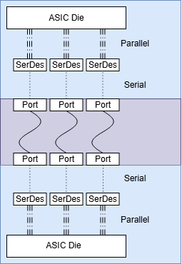
PHY
PHY is abstract, but it ties the hardware side together: it connects physical attributes and hardware to how devices actually communicate on the wire.
PHY (Physical) is a set of components that take hardware 1s and 0s and make them legible for layers above. It also covers additional functions such as error correction (via the aforementioned FEC) and the layers where SerDes lives.
Looking top-down — generating a frame and sending it — PCS is the first sub-layer of PHY. PCS handles encoding and scrambling, adds FEC parity on transmit, and decodes and corrects FEC on receive (important topics, but not ones we'll dig into here).
The next sub-layer is PMA. This is where the SerDes lives, along with CDR and related functions. Specifically here, data converts from the parallel wide bus to the serial single bus.
PMD is the last sub-layer — the medium-facing hardware defined by the implementation. For optical, that includes the optical transmitter/receiver; for DACs, the electrical medium interface; and so on. A retimed optical module can also contain its own SerDes, CDR, and DSP in addition to the host-side PMA.
These three layers together take a frame and enable actual on-wire communication.
- Fiber Light pulses, one after another
- Optical module — PMD Photodiode + TIA: light becomes voltage
- Connector + PCB trace Same serial bits, degrading en route
- SerDes RX at the die edge — PMA Equalize, recover clock, deserialize
- PCS on the die Align lanes, descramble, FEC decode
- MAC — layer 2 Receives the clean frame
- data is serial
- data is parallel
- the conversion point